


Prism Tunnel Diagrams
Prisms are used to fold up optical paths, manipulate image orientations and sizes, and diffract light. In many applications, a combination of prisms are used to achieve several of these effects. In order to design assemblies containing multiple prisms , it is important to understand where light enters, travels, and exits through each prism, and it may also be important to understand the optical path length of the light as it travels through the prism. This can be easily modeled using prism tunnel diagrams.
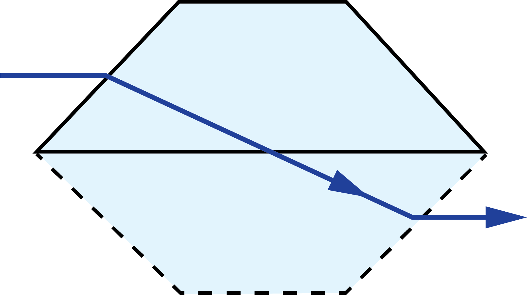
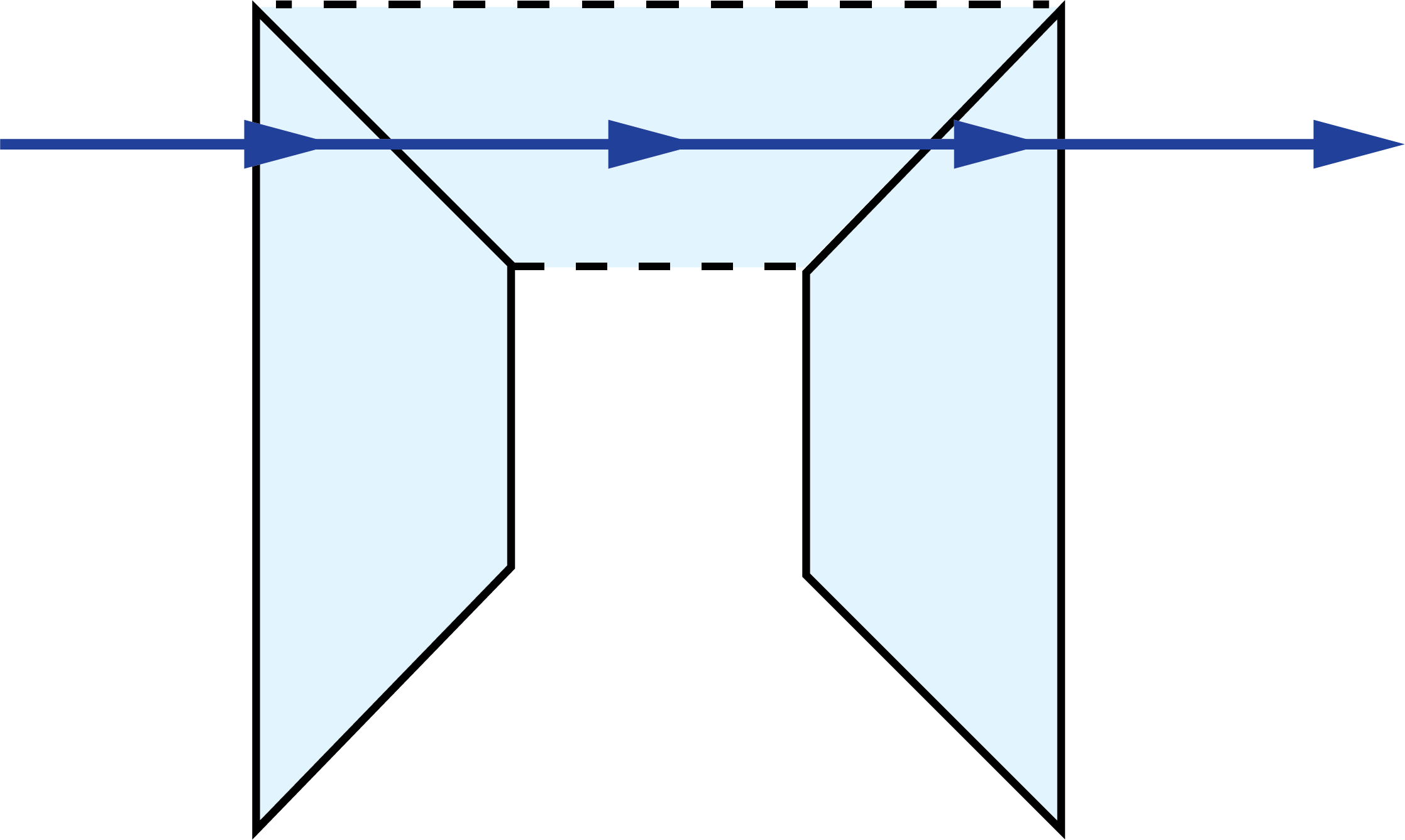
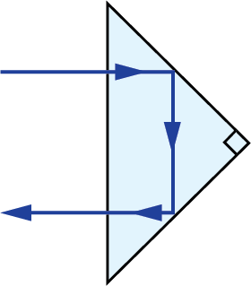
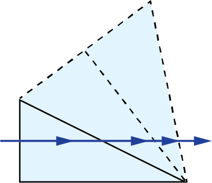
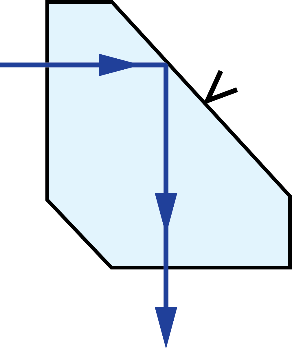
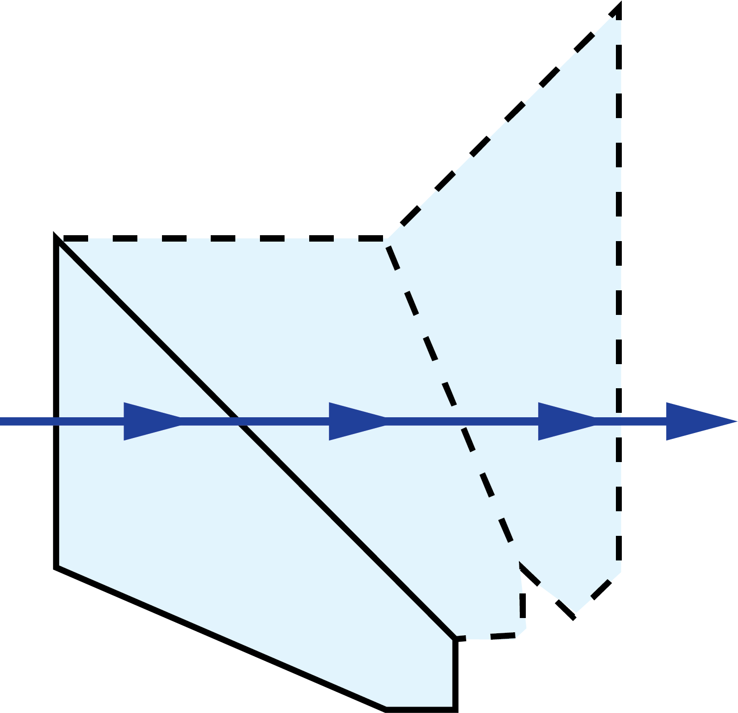
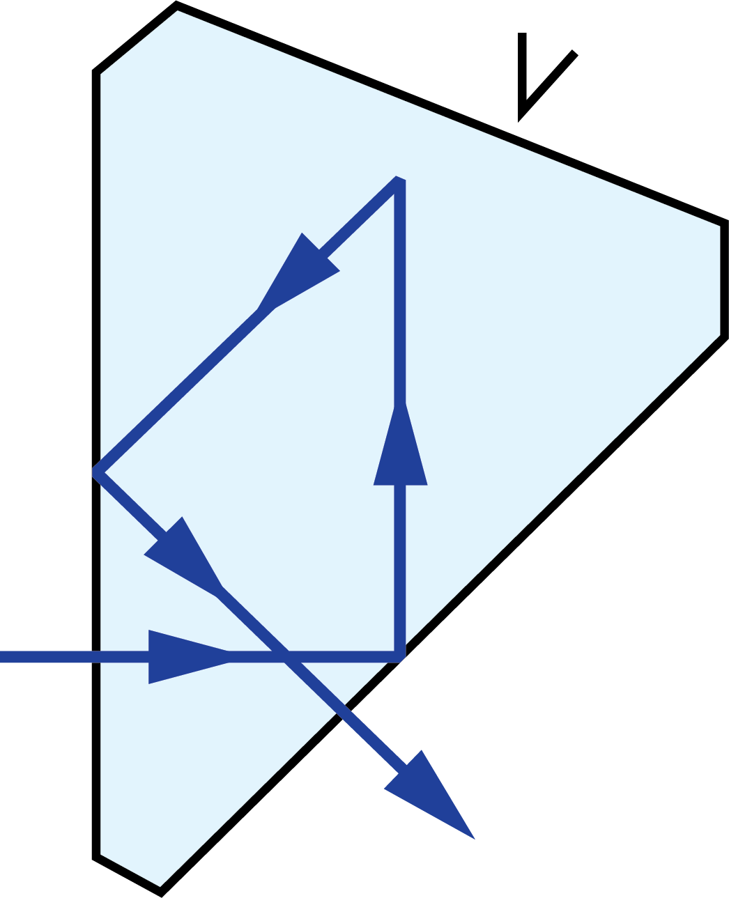
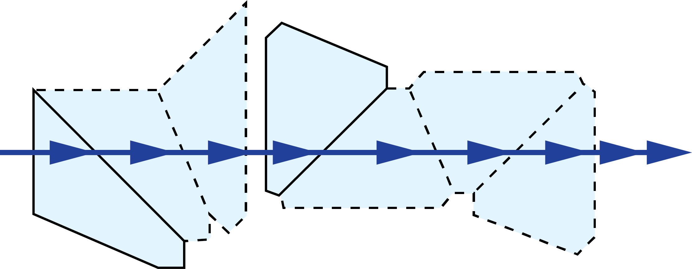
A prism tunnel diagram is a two-dimensional (2D) figure that unfolds the optical path that a ray takes through a prism.1 This technique is used to visualize the total path length through the prism that the rays travel. In this diagram, the prism is represented by the characteristic, to-scale cross-section. A ray starts outside of the prism and enters via one of the faces. Inside the prism, the ray contacts another of the prism’s faces. If the ray strikes the new surface at an angle equal to or greater than the critical angle (associated with the refractive indices of the interfacial media), or if this surface is coated with an appropriate mirror coating, then the light will be totally internally reflected or almost totally and internally reflected. When the ray reflects off of this surface, the cross-section, representing the prism, is flipped over the line representing the reflecting surface of the prism, such that the ray appears to continue straight through the next cross-section without changing its original direction through the first cross-section. If the ray strikes at an angle that is not greater than or equal to the critical angle, and the surface is not mirrored, then the light will pass through this surface and exit the prism. An example of a prism tunnel diagram for a penta prism is shown in Figure 1, beside a typical ray-path diagram.
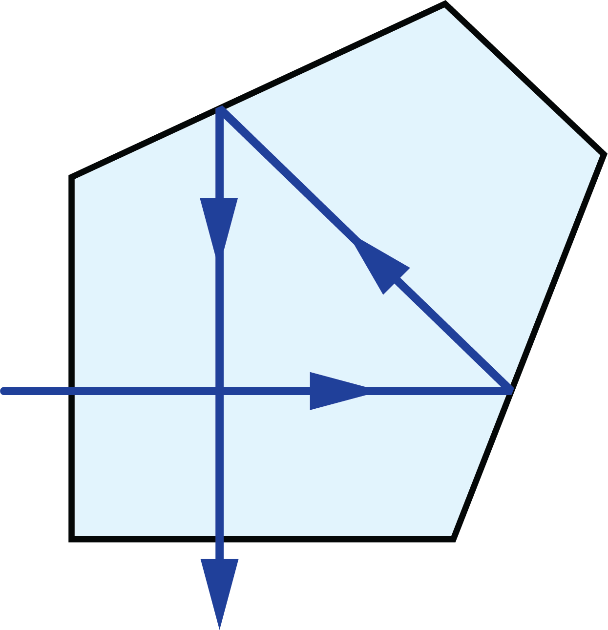
Figure 1: Top: The typical ray-path diagram for a penta prism. Bottom: The prism tunnel diagram for this ray path through the same penta prism.
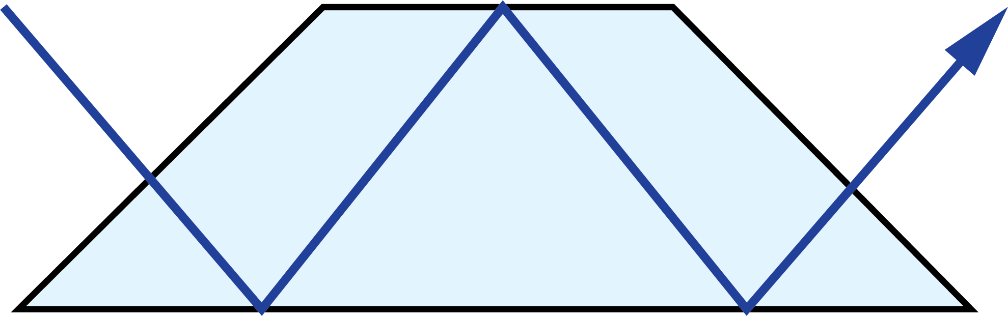
A tunnel diagram helps shows the clear aperture of a prism and can designate where vignetting will occur, determining the prism’s field of view. Prisms can have multiple unique tunnel diagrams for different optical paths through the prism. Unique diagrams can be made for when light enters a prism at a variety of different faces and angles. For example, Dove prisms are commonly used in several different orientations to achieve different types of image transformations. Each of these different ray-traces through the prism have different tunnel diagrams (Table 1).
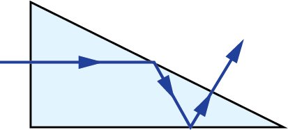
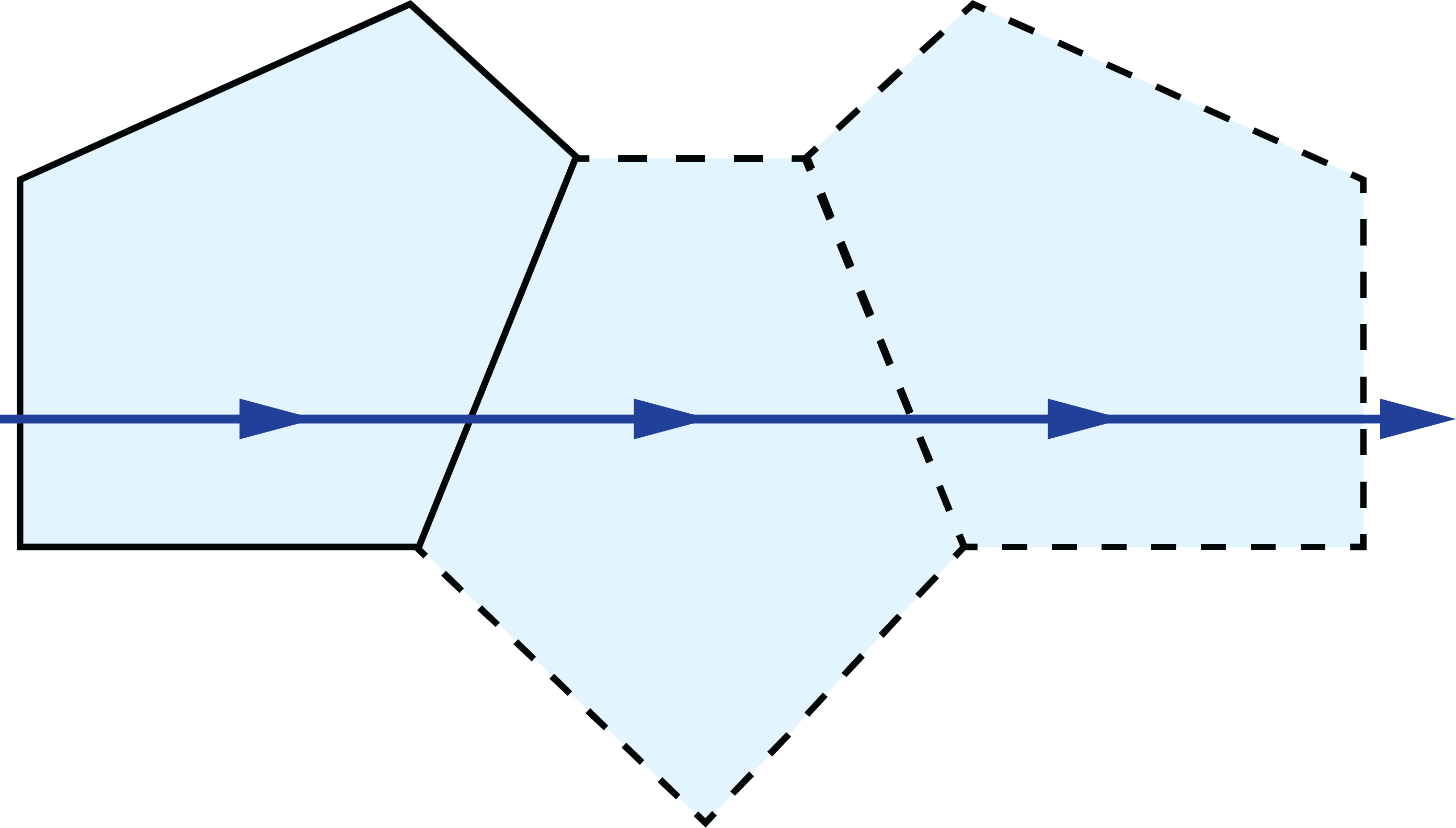
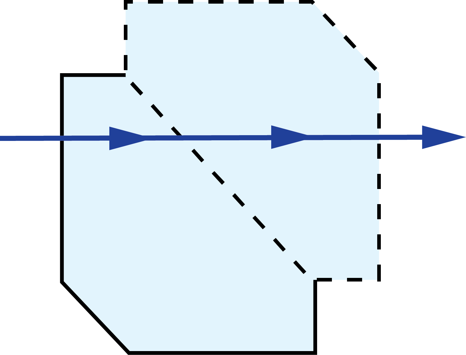
| 2D Ray-Path Diagram | Corresponding Tunnel Diagram |
|
|
 |
 |
 |
 |
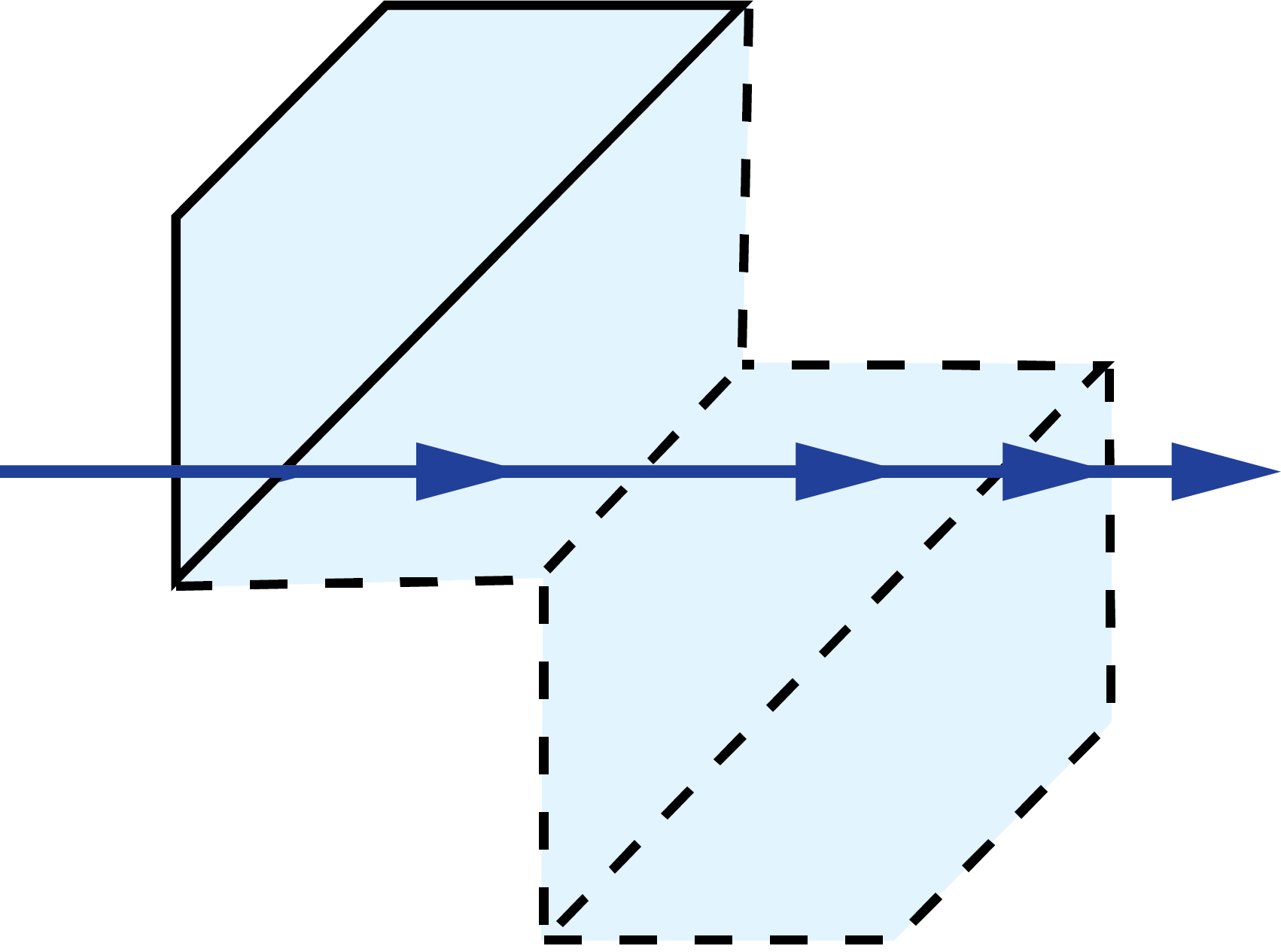 |
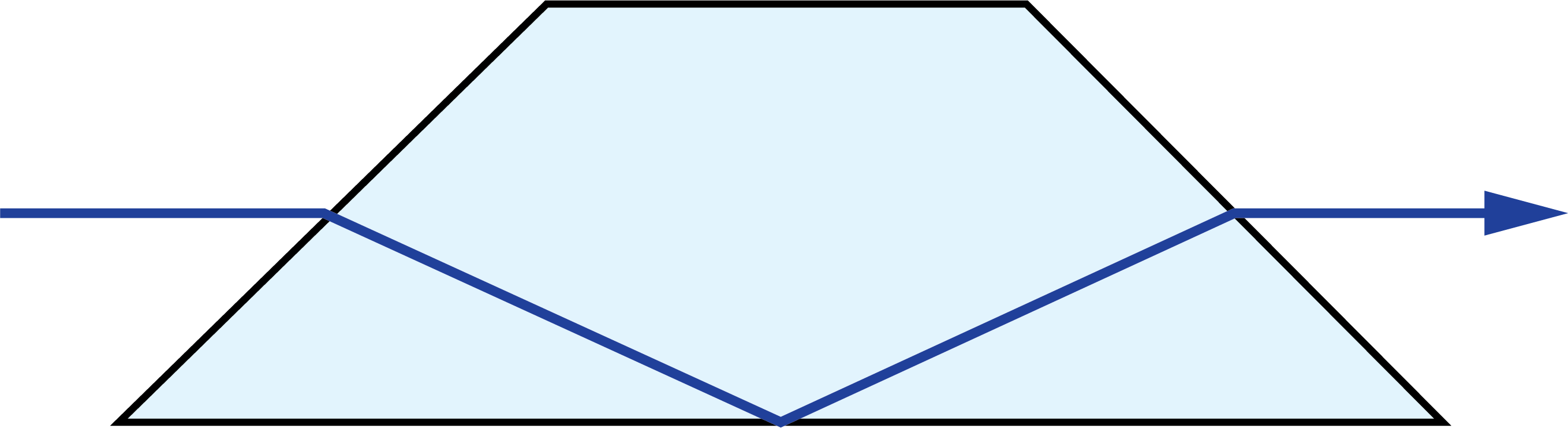
Table 1: Common Dove prism tunnel diagrams
The top and bottom diagrams have light entering and exiting at the same faces, but the angles in which they enter and exit are different. Additionally, the first diagram only has one reflection surface whereas the second and third have two and three reflections respectively.
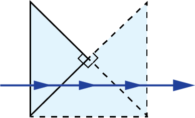
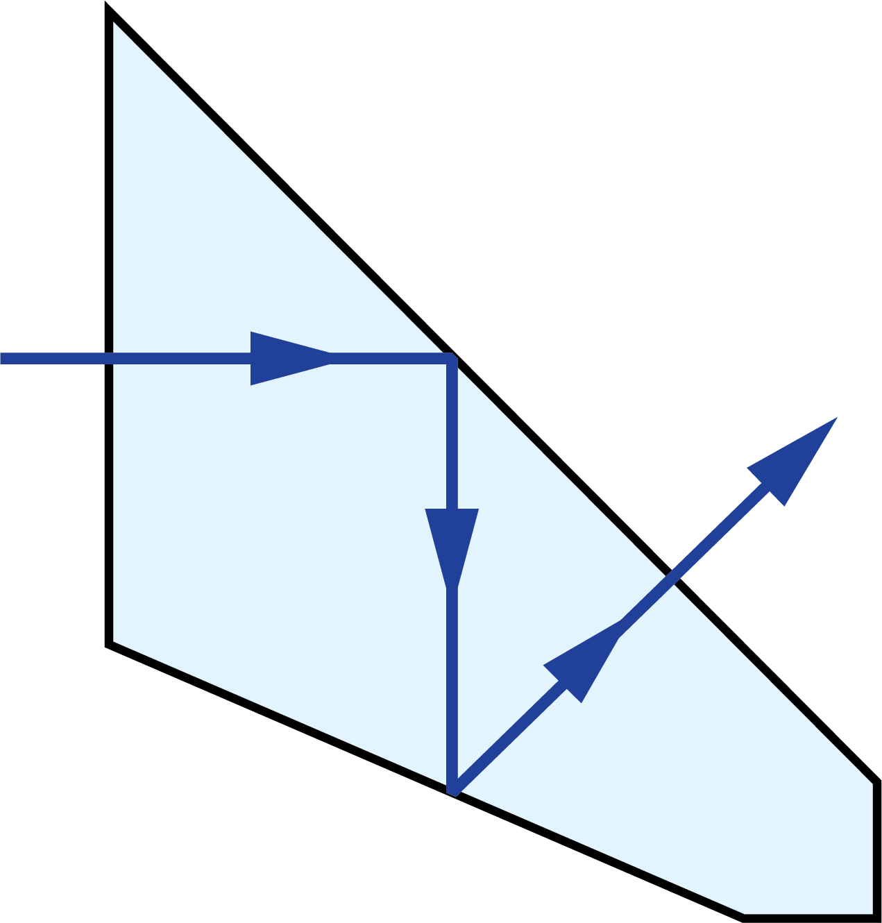
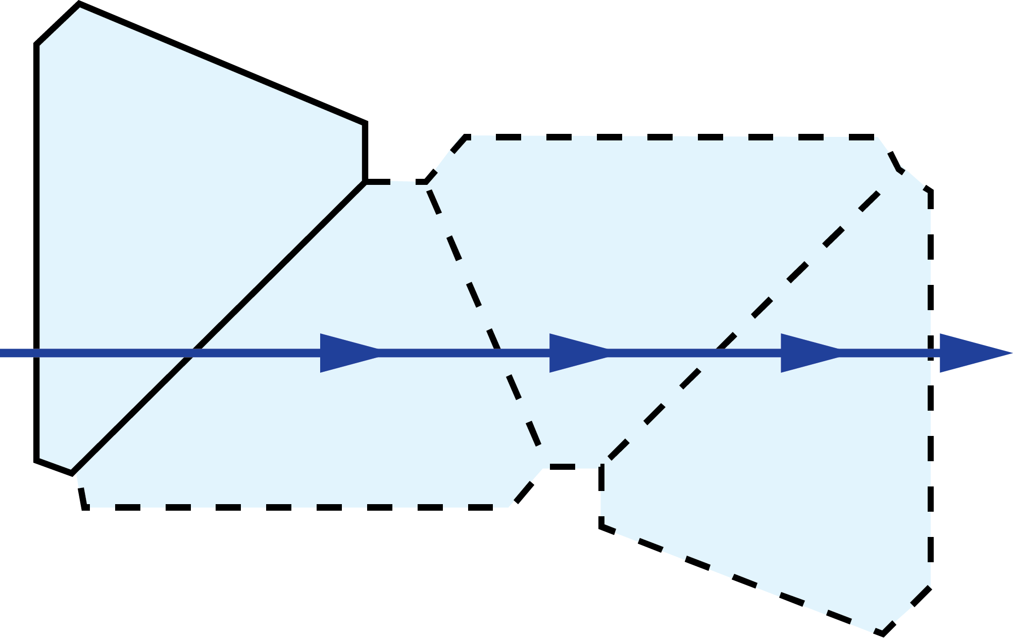
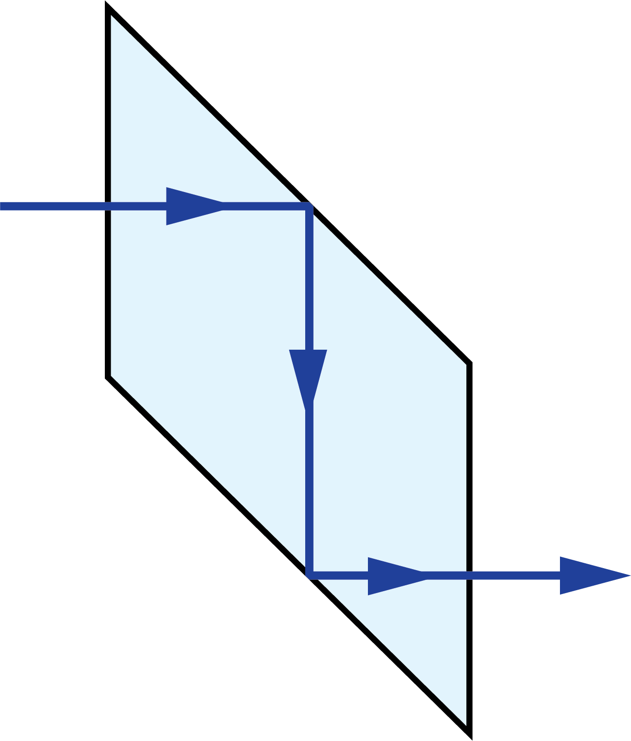
In 2D ray-path diagrams, a “V” symbol is added to indicate a roof, or a section where two faces of the prism meet at a 90° angle and for a “roof-like” shape (Figure 2).2 This causes an additional reflection, changing the parity, or image-handedness.


Figure 2: A “V” symbol is added to the 2D view of the roofed surface of this Amici prism to differentiate it from a non-roofed surface
Reduced Distance
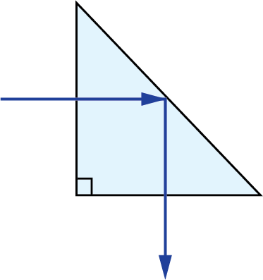
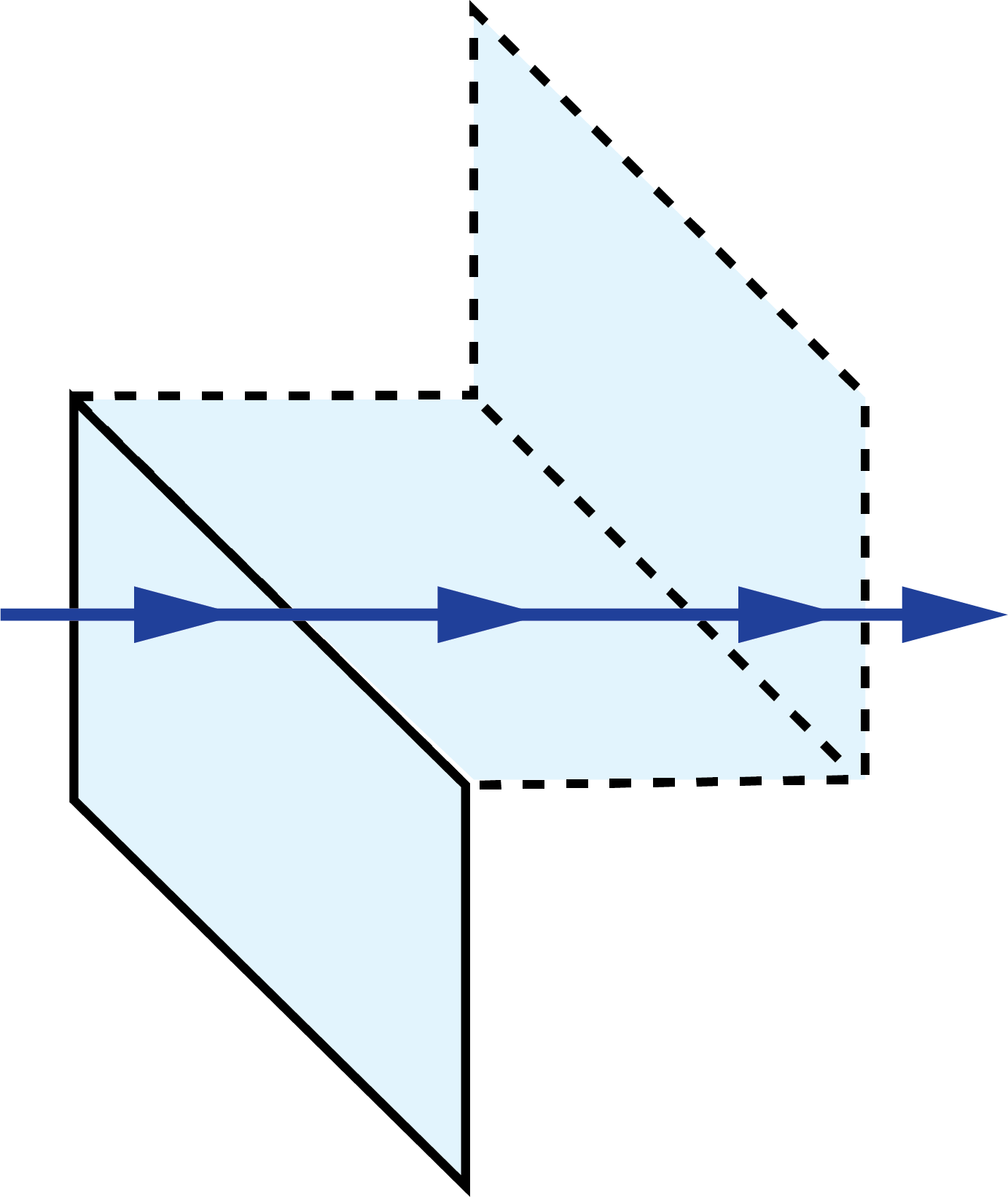
Light traveling through a plane parallel plate will experience an image shift due to diffraction (Figure 3). This image shift is a function of the thickness of the plate (t) and its refractive index (n).
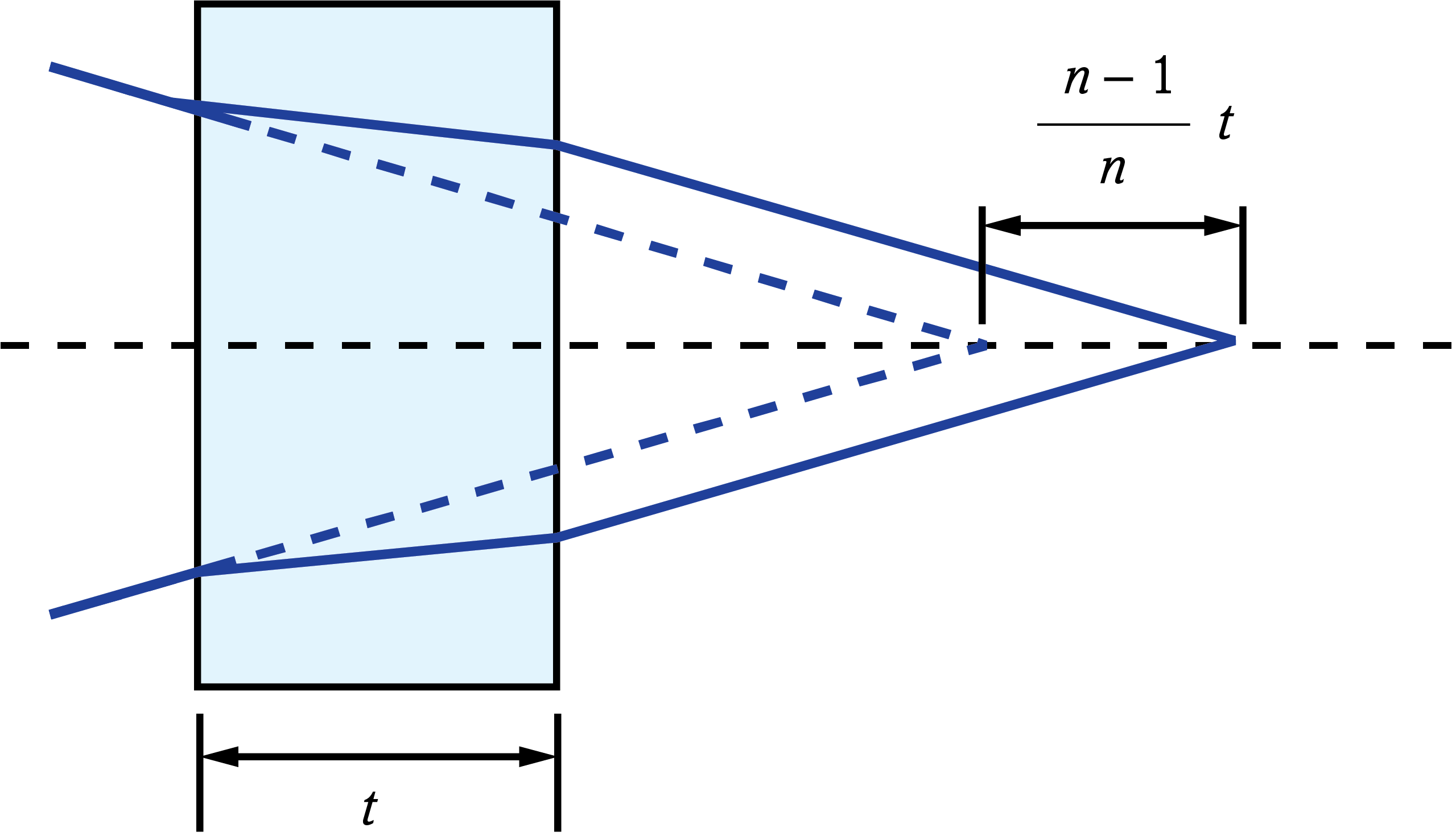
Figure 3: Image shift caused by plane parallel plate
The image shift through the glass can be compensated for by using the replacing the actual path length with the reduced distance. The real path length in the glass (L) is divided by n to result in the reduced distance.2 This is often done in prism tunnel diagrams to determine the air-space equivalent path length through the prism (Figure 3).
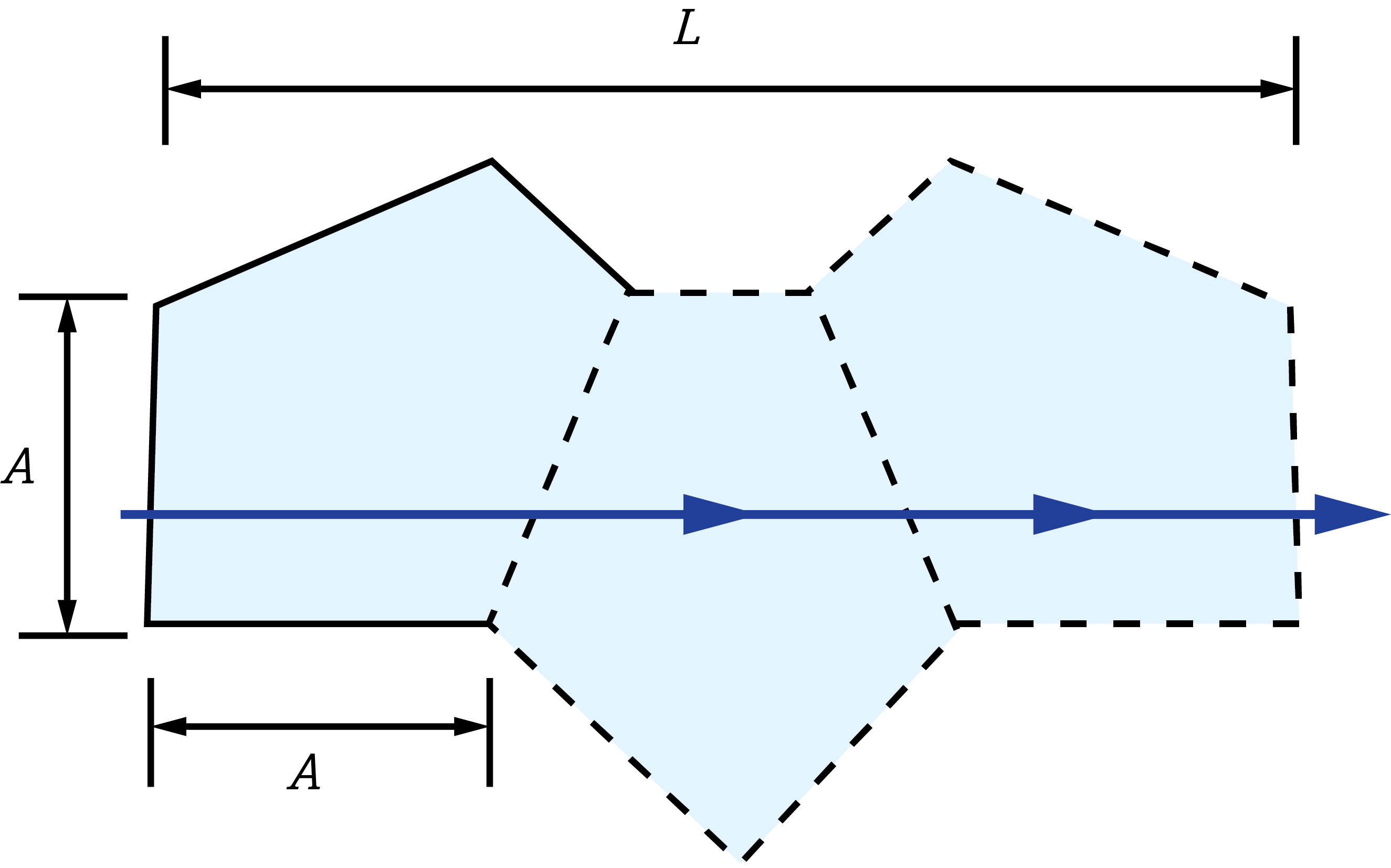
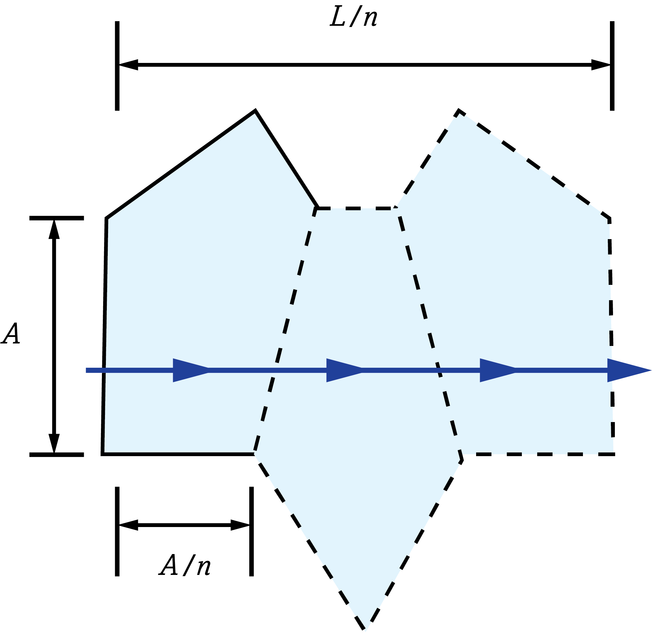
Figure 4: Reduced distance tunnel diagram of a penta prism
Tunnel Diagrams for Common Prism Types
Below is a collection of the unfolded tunnel diagrams for common prism types. The given optical path length is the actual distance light travels in the prism, not the reduced distance. To determine the reduced distance, divide the optical path length by the refractive index of the prism.
Right Angle Prisms:
 |
|
| 3D Ray-Path Diagram | 2D Ray-Path Diagram | Corresponding Tunnel Diagram | Optical Path Length |
 |
|
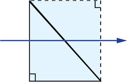 |
$$ A $$ |
 |
 |
 |
$$ A $$ |
Littrow Dispersion Prisms:
 |
|
| 3D Ray-Path Diagram | 2D Ray-Path Diagram | Corresponding Tunnel Diagram | Optical Path Length |
 |
|
 |
$$ A \sqrt{3} $$ $$ \approx 1.7321 A $$ |
Penta Prisms:
 |
|
| 3D Ray-Path Diagram | 2D Ray-Path Diagram | Corresponding Tunnel Diagram | Optical Path Length |
 |
|
|
$$ A \left( 2 + \sqrt{2} \right)$$ $$ \approx 3.4142 A $$ |
Amici Roof Prisms:
 |
|
| 3D Ray-Path Diagram | 2D Ray-Path Diagram | Corresponding Tunnel Diagram | Optical Path Length |
|
|
 |
$$ \left( 1 + \frac{\sqrt{2}}{2} \right)A $$ $$ \approx 1.7071A $$ |
Dove Prisms:
 |
|
| 3D Ray-Path Diagram | 2D Ray-Path Diagram | Corresponding Tunnel Diagram | Optical Path Length |
 |
|
|
$$ \frac{2 n A}{\sqrt{2 n^2 - 1} - 1} $$ |
 |
|
|
$$ B $$ |
Half-Penta Prisms:
 |
|
| 3D Ray-Path Diagram | 2D Ray-Path Diagram | Corresponding Tunnel Diagram | Optical Path Length |
 |
|
 |
$$ \frac{A}{2} \left( 2 + \sqrt{2} \right) $$ $$ \approx 1.7071 A $$ |
Schmidt Prisms:
 |
|
| 3D Ray-Path Diagram | 2D Ray-Path Diagram | Corresponding Tunnel Diagram | Optical Path Length |
 |
|
 |
$$ A \left( 2 + \sqrt{2} \right) $$ $$ \approx 3.4142 A $$ |
Pechan Prisms:
 |
|
| 3D Ray-Path Diagram | 2D Ray-Path Diagram | Corresponding Tunnel Diagram | Optical Path Length |
 |
 |
 |
$$ \left( 2 + \sqrt{2} \right) \left( \frac{ A_{\tiny{\text{Half-Penta}}}}{2} + A_{\tiny{\text{Schmidt}}}\right) $$ $$ \approx 3.4142 \left( \frac{A_{\tiny{\text{Half-Penta}}}}{2} + A_{\tiny{\text{Schmidt}}} \right) $$ |
Rhomboid Prisms:
 |
|
| 3D Ray-Path Diagram | 2D Ray-Path Diagram | Corresponding Tunnel Diagram | Optical Path Length |
 |
|
 |
$$ 2D $$ |
References
- Greivenkamp, John E. Field Guide to Geometrical Optics. SPIE Optical Engineering Press, 2004.
- Hopkins, R. E., “Mirror and Prism Systems," in Military Standardization Handbook: Optical Design, MIL-HDBK 141, U.S. Defense Supply Agency Washington, DC, 1962.
- Shack, Roland V. “Prisms.” In OPTI 421/521 - Introductory Optomechanical Engineering, University of Arizona, 2016.


或查看各区域电话
报价工具
只需输入商品编号
Copyright 2023, 爱特蒙特光学(深圳)有限公司。— 广东省深圳市龙华工业东路利金城科技工业园3栋5楼 518109 - 粤ICP备2021068591号