


Keys to Cost Effective Optical Design and Tolerancing
As most designers know, optical design software can be a powerful tool. But it's just that, a "tool". The proper interpretation of optimized results is just as important as the input of correct information. That is why experienced designers weigh the advantages and disadvantages of using one lens design code over another prior to any actual design. But with growing industry demands, designers need to incorporate all aspects of production into their design in order to ensure that the final product will be brought successfully to market. Designers need to not only be aware of the nuances of fabrication, assembly, coating, etc, but also with how to integrate costs with the demands of the intended application. Unfortunately, no software provides a subroutine to assure that costs are minimized.
The need to minimize costs is addressed by off-the-shelf catalog lenses, which have the dual advantage of being inexpensive compared to a small custom production run as well as being immediately available. Stock lenses can be integrated into custom multi-element designs, yielding significant cost savings at a marginal sacrifice in performance. In some cases, stock lenses may not be practical for manufacturing a given application but may be suitable for fast prototyping. In addition, the readily available prescription data for most lenses and even many multi-element lenses are encouraging designers to use stock lenses (see Figure 1).
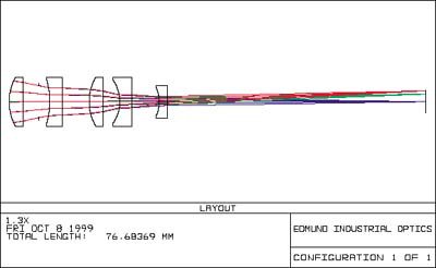
Figure 1: Ansys Zemax OpticStudio Optical Design Software
Knowledge of manufacturing practices allows designers to construct the most economical solution. By investing some time at a local optics shop, designers can experience firsthand the fabrication techniques employed by an optician. Choices made during the design stage that appear inconsequential can prove to be crucial.
For example, the simple act of making elements equi-convex or equi-concave can eliminate problems and save costs in seemingly unrelated processes such as assembly. Ask any assembler how they feel about lenses that have nearly the same radii on their outer surfaces, and they will tell you stories of multiple tear-downs to correct for lenses mounted in the wrong direction. In order to avoid this added cost select equi-convex or equi-concave lenses. These lenses can also reduce the cost of test plates and reduce production time.
Any design starts with a given application and the known values associated with it. It's the designer's job to solve for the unknowns, typically by regarding certain specifications like radii as variables while holding other values constant. Values typically held constant include: diameter, center thickness, and glass material.
Selecting the Diameter
Once clear apertures have been determined, it is important that designers understand how the lens will be mounted, ground and polished. The final lens diameter should be chosen to accommodate lens mounting (see Figure 2).
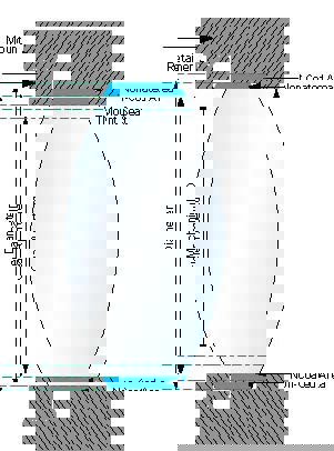
Figure 2: Mechanical Mounting Considerations
When mounting on a mechanical inner diameter (based on contact points with the radii), glare may result from light reflecting off a spacer, retainer ring or mounting seat/shelf. In comparison, light reflecting off a larger inner diameter (ID) will be cut-off by the system's aperture. If the element is coated, the diameter of the coating area should be larger than the mounting ID in order to avoid exposure of uncoated lens surface areas.
Typically, elements in the 20 - 40 mm range require a diameter 3 mm larger than the clear aperture diameter. In order to produce repeatable lenses, manufacturers typically use lens blanks (glass in a pre-fabricated state) that are 2mm larger than the specified lens diameter. This method of "oversizing" allows the optician to remove defects during the final centering process. One common defect, called "edge-roll," (see Figure 3) is a surface deformation that results from the excessive wear that polishing tools exert on the edge of a lens blank.
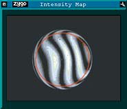
Figure 3: Interferogram of PCX lens showing "edge-roll"
Another defect, often referred to as "wedge," occurs when the optical and mechanical axes of an element do not coincide. This centration error can be corrected by aligning the centerline of the lens surfaces with a spindle that rotates about the mechanical axis. The blank is then ground down to the final lens diameter, while being aligned with the optical axis. This in turn defines the diameter tolerance.
The deviation angle specification is used to limit the amount of centration error. It is important for a designer to consider deviation angle when reviewing the effect of compounding errors on the alignment of a multi-element system. Not only must each lens be axially aligned, but the optical assembly must also be aligned to the housing.
The main consideration of working with oversized blanks is that the edge thickness of a bi-convex or plano-convex element be smaller than the final lens diameter. The designer can incorporate this consideration into the design process by using lens diameters that are typically 10% - 20% larger than the final diameters, something accomplished by including a minimum edge thickness operand in the merit function of their chosen software.
Selecting the Center Thickness
Typically, a designer will steer designs away from large center thickness values in order to control the material volume, and thus the weight of the final product. Usually as a result of color correction, design software will tend to favor thin lenses with high diameter:center-thickness ratios. If kept below 10:1, the diameter:center-thickness ratio rarely affects cost. When the ratio approaches 15:1, costs begin to rise for low power lenses with longer radii, as well as for meniscus lenses. These types of lenses exhibit "springing" during conventional and high-speed manufacturing. In conventional polishing, lenses are placed on a blocking tool with hot sticky pitch. After polishing, the lenses are removed from the polishing block by chilling the pitch to a brittle state, allowing easy separation from the lens surfaces. Surfaces can deform when stress, introduced in the blocking process, is removed.
For high-speed manufacturing, the effect is manifested differently. Increased speed and pressure causes the lens to oscillate, resulting in deformities and making irregularity (surface shape) difficult to control.
The effect of the diameter:center-thickness ratio on cost can vary by lens shape and is actually less cost sensitive for large negative power lenses. Large negative power lenses also have large edge thickness values that provide support to handle pressures and stress.
Selecting the Glass Material
There is almost as much variety in glass materials as there is in cost of glass. For example, if we assign the most commonly used optical grade glass BK7 an arbitrary cost value of 1, then SF11 would have a price value of 5 while LaSFN30 would be 25. Material properties that can drive up costs include high staining and softness, which are often difficult to work with and which require careful handling. It is important to note that these properties can affect production during both fabrication and coating.
Design software often provides an option to "model" a glass type, allowing index and dispersion values to vary continuously. Although this variation will usually produce quicker results, caution should be used. If this modeling option is selected, the designer must diligently monitor the design to steer it away from expensive and difficult-to-control glass types. Many optical designers will use a personalized glass catalog, usually containing glass types that are less expensive, readily available and possess other desirable characteristics. This method, although slower, may provide for a less expensive design.
Using Tolerancing Schemes
Once the initial design is completed, the designer's next task is to assign appropriate tolerances to the various parameters. Diameter, wedge, power/irregularity and center thickness tolerances all need to be assigned for each element. Design performance will be more sensitive to some of these tolerances, while other areas will be little affected (see Figure 4). The designer can use tight tolerances in sensitive areas and permit broader or looser tolerances in other areas. Additionally, many optical shops have varying degrees of success controlling specific tolerances. By getting to know the strengths and weaknesses of various optical shops, as well as their associated costs, designers can streamline the process by directing designs to appropriate vendors.
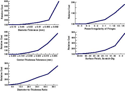
Figure 4: The Effect of Relative Costs are shown for Various Parameter and Tolerance Specifications. The value 100 represents the cost of a basic element. Source: See Reference #2
Tolerancing runs performed by most design software assume Gaussian distribution, with errors equally distributed about the nominal value. However, some parameters tend to be skewed either to the plus or minus end of the scale during manufacturing. Opticians tend to polish lenses on the plus side of a center thickness tolerance. By leaving extra material, the optician can rework lenses should they be damaged during later stages of fabrication.
Another trend is the practice of polishing surfaces on the "low" side. When using a test glass to monitor power tolerances, the optician will avoid center contact in favor of edge contact in order to prevent scratching the polished surface and the test glass (see Figure 5). As a result, the power tolerance is cut in half and thus convex/concave surfaces will be flatter/sharper than the nominal value.
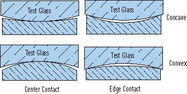
Figure 5: Polishing on the "low side"
Finally, the presentation of the tolerancing must be interpretable by opto-mechanical designers. By emphasizing the sensitive areas of a design, a designer can help ensure a successful opto-mechanical design. Emphasizing axial position over individual spacing tolerances, for instance, can better control fixed flange distance requirements that may suffer due to the "stacking" of individual errors.
There are several other topics that should also be considered. These topics include but are not limited to: coating, surface accuracy (power/irregularity), and surface quality (scratch-dig). By being aware of what goes on after a design is put into production, a designer can be better prepared to integrate the relevant issues before and during the actual design. If you would like to contact us regarding prescription information, design requirements, or a specific application, please Contact us.
References
- "Understanding Optical Specifications." Edmund Optics.com. November 2, 2010. http://www.edmundoptics.com/resources/application-notes/optics/understanding-optical-specifications.
- Hudyma, Russell, Michael Thomas, and Yvonne A. Carts. "Reasonable Tolerancing Aids Cost-effective Manufacture of Optics." Laser Focus World, May 1, 1991.
- Smith, Warren J. "Optical Component Specifications: Avoiding Pitfalls in Setting Tolerances for Optical Components." In The Photonics Design and Applications Handbook, 346-49. 45th ed. Pittsfield, MA: Laurin Publishing, 1999.


或查看各区域电话
报价工具
只需输入商品编号
Copyright 2025, 爱特蒙特光学(深圳)有限公司 粤ICP备2021068591号
The FUTURE Depends On Optics®