您选择的产品已被添加至购物车
TECHSPEC® components are designed, specified, or manufactured by Edmund Optics. TECHSPEC® 组件由爱特蒙特光学设计、规定或生产。 了解更多

Beamsplitter Compensation Plate, Fused Silica, 25mm Dia, VIS

×
产品编码 #89-743 新产品 9 库存
Quantity Selector - Use the plus and minus buttons to adjust the quantity. +
RMB 1,718.73
所示库存数量系全球库存总量,非本地现货。
如需查询具体库存分布位置,可将产品加入购物车进行查看。
本价格为含税价
含税批量价格
数量 1-10 RMB 1,718.73 each
数量 11-25 RMB 1,374.98 each
Need More? 索取报价
下载产品资料

规格

物理和机械特性

倒角:
Protective as needed
有效孔径 (%):
90
有效孔径 CA(mm):
22.50
直径 (mm):
25.00 +0.00/-0.10
边缘:
Fine Ground
厚度 (mm):
3.00 ±0.20
Wedge Angle (arcmin):
30 ±1

光学特性

入射角 (°):
45
涂层:
45° AOI BBAR (400-700nm)
涂层规格:
S1 & S2: Rabs ≤ 2.0% from 400-700nm @ 45° AOI
Ravg ≤ 1.0% from 400-700nm @ 45° AOI
基底: Many glass manufacturers offer the same material characteristics under different trade names. Learn More
Fused Silica (Corning 7980)
表面平整度 (P-V):
λ/10 @ 632.8nm
表面质量:
20-10
波长范围 (nm):
400 - 700

合规性

RoHS 2015:
Certificate of Conformance:
Reach 253:

产品概览

  • λ/10 熔融石英基底
  • 提供适用于可见光(VIS) 和近红外(NIR) 的增透膜(AR) 镀膜选项
  • 专为与 TECHSPEC λ/10 平板分光镜配合使用而设计

TECHSPEC 分光镜补偿板旨在使采用 45° 入射角平板分光镜的系统中的光程长度保持一致。这些窗口采用精密熔融石英制造,可确保透射光束和反射光束经过相同的材料厚度,从而保持相位完整性和波前质量。与 TECHSPEC λ/10 平板分光镜配合使用时,补偿板有助于最大限度降低色散,并在严苛光学系统中保持高干涉对比度。TECHSPEC 分光镜补偿板具有 30 arcmin 楔角,可最大限度减少内部干涉和背反射,使这些补偿器成为精密应用的出色选择。这些补偿板非常适合需要精确光路匹配的干涉测量、计量检测和光谱应用。

在 Michelson 和其他干涉仪中使用时,分光镜可能因其厚度而导致光程长度和色散出现微小差异。补偿板可以校正这种差异,在宽带系统中尤其有用。选择补偿板时,应确保补偿板与所使用的分光镜具有相同的基底和厚度,以实现正确的光程长度调整。

技术数据

Graph showing typical transmission percentage of 45° AOI beamsplitter with 400-700nm AR coating across wavelength range
Transmission percentage chart of 45° AOI beamsplitter with AR coating from 700 to 1100 nm wavelength
Reflectivity chart showing typical reflectivity of 45° AOI beamsplitter with 400-700 nm AR coating across wavelength range
Reflectivity curve of 45° AOI beamsplitter with 700-1100 nm AR coating showing typical reflectivity percentage
Beamsplitter Compensator Plates
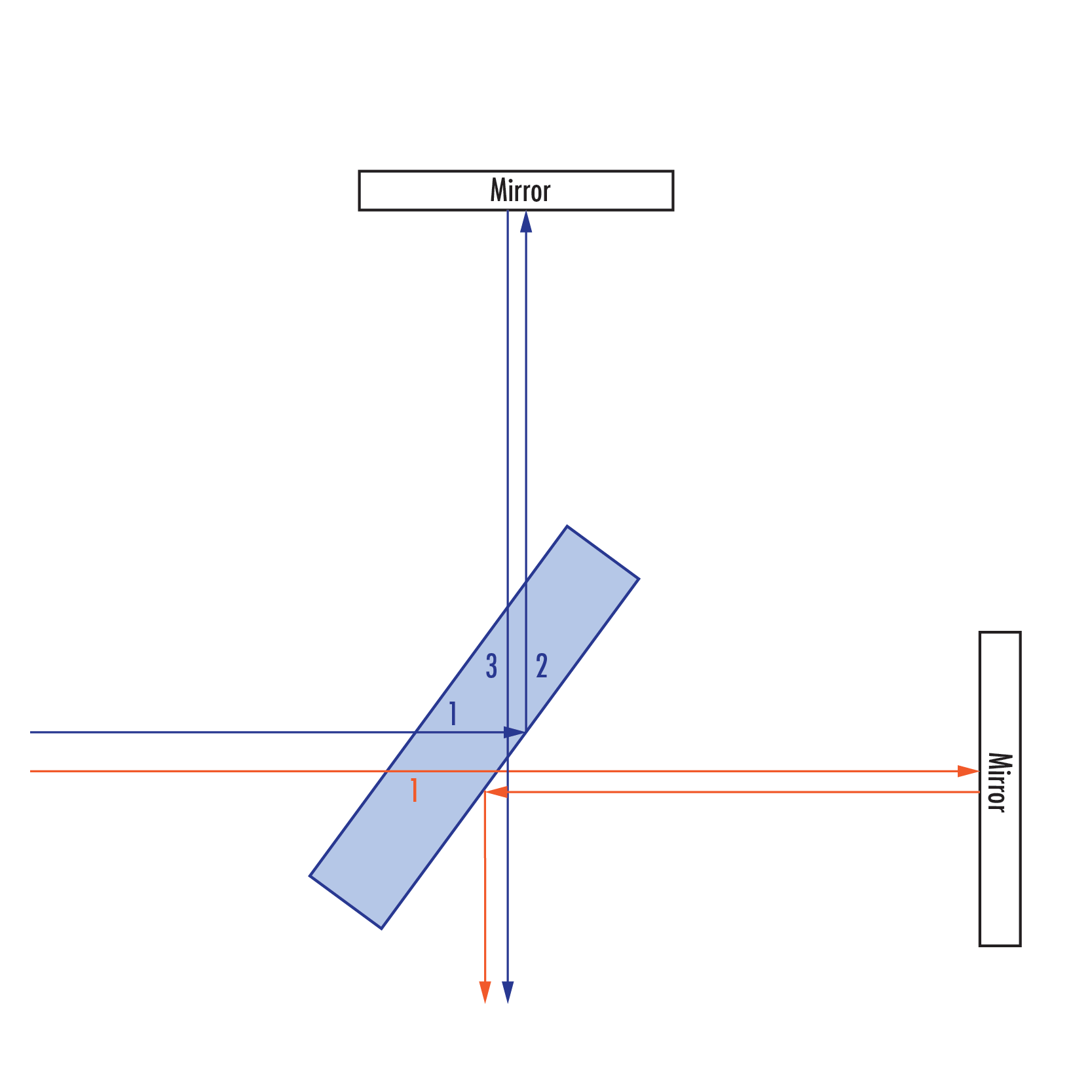
Diagram showing beam path in an uncompensated interferometer setup. (Please note, reflected beams are depicted offset for demonstrative purposes).  Numbers refer to number of passes through the beamsplitter substrate. The blue beam (initially reflected at the beamsplitter) travels through the beamsplitter substrate three times, while the orange beam (initially transmitted through the beamsplitter) travels through the beamsplitter only once. This results in a differing path length and dispersion between the two beams once they arrive at the sensor.
Diagram showing beam path in an uncompensated interferometer setup. (Please note, reflected beams are depicted offset for demonstrative purposes). Numbers refer to number of passes through the beamsplitter substrate. The blue beam (initially reflected at the beamsplitter) travels through the beamsplitter substrate three times, while the orange beam (initially transmitted through the beamsplitter) travels through the beamsplitter only once. This results in a differing path length and dispersion between the two beams once they arrive at the sensor.
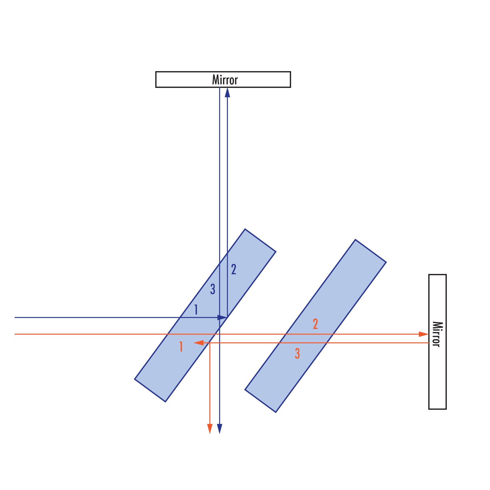
With the addition of a compensator plate of the same thickness and refractive index of the beamsplitter, the orange beam now experiences the same change in path length and dispersion as does the blue beam.

Coating Curves

 
销售和技术专家咨询电话
 
或查看各区域电话
一键式
报价工具
只需输入商品编号